
Hydraulic Winch Options & Accessories
Winch Options
Rope Guide
- Rope guides are available for the C and W series winches.
- Rope guides correct minor misalignments when pulling a load that can move out of alignment. They are designed to be used only as a guide and should not be used at sharp angles or in a position where the rope guide is supporting the load.
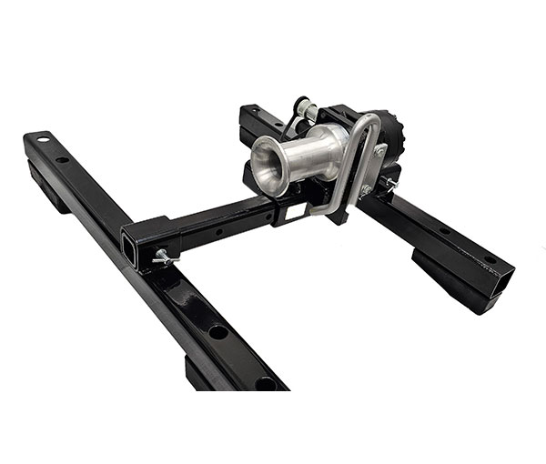
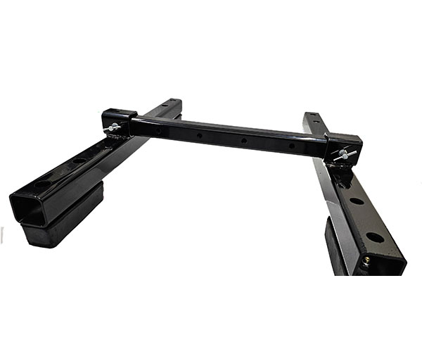
Pivot Link
- The Pivot Link connects any of the adapter mount winches to a receiver hitch and pivots to allow the winch to self align.
- Made from 2 inch square tubing
- Weight 28 lbs.
Dual Counterbalance Valve
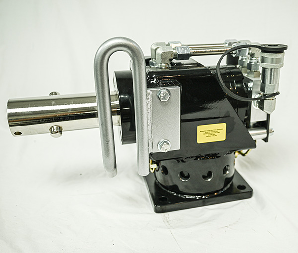
Optional mounted dual counterbalance valves are available for the B, CH, CL, and LS series winches in a configuration similar to that shown above. A manifold style mounted version comes standard on the LHB series.
- Counterbalance valves provide several benefits. They allow a winch to be reversed under load. They offer protection from hydraulic failures by blocking the flow to and from the hydraulic motor whenever there is no flow going to the winch. They also modulate the flow when a control valve is suddenly closed.
- When reversing a winch under load, a dual counterbalance valve should be used. If reversed under load without counterbalance valves, the force of the load can pump oil out of the winch faster than it is coming in, allowing the load to run away or drop.
- Counterbalance valves use a control valve that does not block the flow in neutral, otherwise pressure can get trapped between the control valve and the counterbalance valve and cause the counterbalance valve to malfunction.
- Our winch mounted dual counterbalance valve (as shown on a B30-RF) has all steel lines between the valve and hydraulic motor.
- If a winch is used without counterbalance valves, the control valve should block the flow in neutral to hold the load and should not reverse. A capstan does not necessarily have to reverse. The load on a capstan can be released by allowing the rope to slip on a stationary drum.
- The maximum operating pressure must be limited to 2300 psi with the dual counterbalance valve option.
Foot Control
Valve
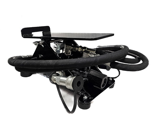
- FV series control valves have an adjustable relief valve that can be used to drop existing circuit pressures to the desired operating pressure.
- Adjustable stops can limit or block pedal travel in either direction. The stops can be used to limit the flow to some extent. For precise metering, a separate flow control would be necessary.
- The FV-2T is a tandem center type valve. In neutral, flow to the winch is blocked to hold the load and incoming oil flows through the valve to the outlet. This valve should be used with the reverse stop adjusted to block the reverse flow.
- The FV-2M is a motor spool type valve. In neutral, ports to the winch are free flowing to the outlet and incoming oil flows through the valve. This valve is for use with the dual counterbalance valve option. Without counterbalance valves, the winch would freewheel in neutral.
- Flow rating: 20 GPM.
- Maximum pressure: 3000 PSI.
Manhole / Vault Kits
- The CH-MVK manhole and vault kit is shown in the first picture. It is the stronger kit for use with a CH series adapter mount winch. The weight is 56 lbs.
- The second picture is the WP-MVK manhole and vault kit. It is for use with the CL or WP series adapter mount winches. It can also be used with the CH series if the capacity is less than 2400 lb. The weight is 35 lbs.
- Both kits pin together and have 4 skid resistant rubber pads. The width and winch position is adjustable.
- The winch in the first picture is a CH50-A.
- The winch in the second picture is a WP3-SP. The WP3-SP is designed specifically to be used with the manhole and vault kit and has a built in rope guide.
Product List - Contact Us for Pricing
C series rope guide
L series attachment plate
Winch mounted dual counterbalance valve
Drum lock option for LS winches (only on LS-50)
Foot control valve without hoses or couplings
Foot control valve with winch side hoses and quick couplings
Pivot link
RC / RF receiver adapter
CH-MVK manhole & vault kit
WP-MVK manhole & vault kit
Additional Products
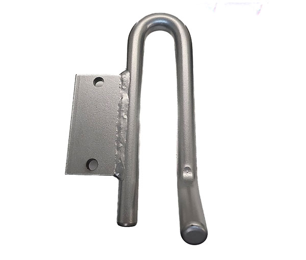
Attachment Plate
- Attachment plates are available for L series winches. They can be used for connecting safety lines, guide lines, guides, etc. They attach with 2 bolts and can be easily removed. The winch frame is not drilled and tapped for the bolts unless the attachment plate is ordered with the winch
- The total combined load from all of the attachments plus the load on the winch drum must not exceed the winch capacity
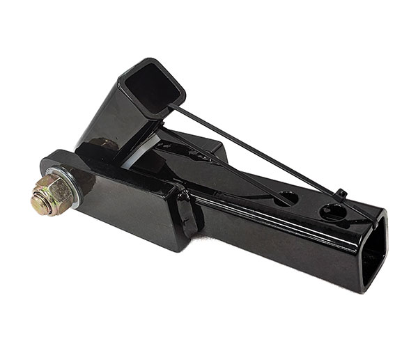
RC / RF Adapter
- Connects L series RC mount or C series RF mount winches to a receiver hitch
- The base can remain bolted to the adapter and the winch can be removed by removing the locking pin
- Made from 2 inch solid square tube
- 2,000 lb. capacity
- Weight: 29 lbs
- One of our heavier winches is the LHB7-RC. The weight of the winch should be taken into consideration for portable applications
Drum Lock (only available on the LS-50)
- The drum lock option is available for LS series winches. The option includes machined notches in the capstan and a locking lever with mounting lug. Without the drum lock option, the back rim of the LS capstan is smooth without any notches
- The winch brakes and holds the load hydraulically. Internal clearances in the hydraulics can allow the drum to slowly creep back. The ratchet type action of the locking lever, locks the reverse direction of the capstan. This allows the load to be held for an extended period of time without drifting out of position
- The reverse must be disabled to prevent the operator from inadvertently locking a moving drum. The impact force from locking a moving drum could damage the winch or the load. If connecting to a dual direction control valve, a one way check valve can be installed in the return line to block the reverse
Spring Applied, Hydraulically Released Brake (option just on the LHB Winches)
- LHB series capstan winches have a spring applied, hydraulically released multi-disc wet brake. The brake eliminates any hydraulic drift and offers additional protection in the event of a hydraulic failure
- The LHB model features a manifold style mount dual counterbalance valve as standard equipment and is fully reversible
- LHB winches must be used with a motor spool type control valve, that does not block the flow in neutral. Valves that block the flow in neutral can trap oil in the brake release cavity and prevent the spring brake from applying. A case drain line is required for LHB models only
- The LHB is actually an alternate for the LH series instead of an option. Many of the components are different and it is not practical to convert a LH to a LHB
- RF and F mounts are also available for the LHB series